

 العربية

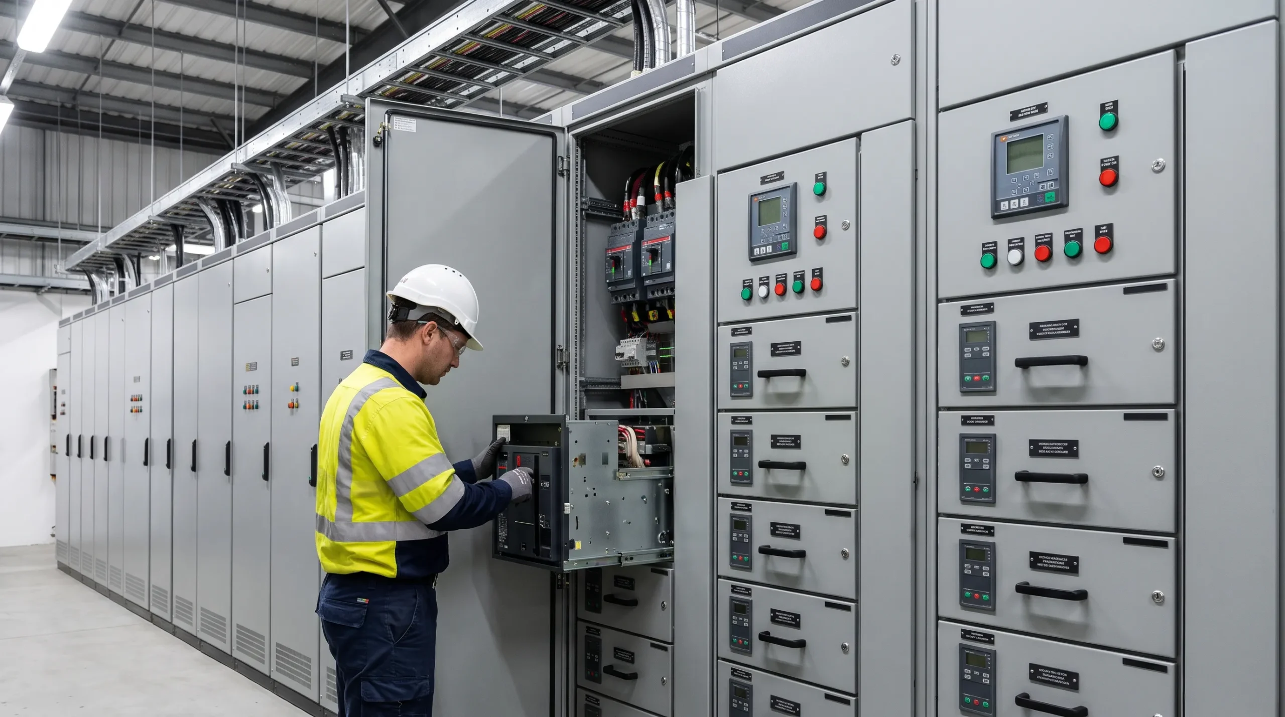
In modern industrial facilities, process uptime and electrical safety depend entirely on how efficiently motors are powered, controlled, and protected. Across manufacturing plants, water treatment facilities, and heavy processing environments, electric motors consume the vast majority of industrial power. Operating dozens or hundreds of motors with scattered, standalone wall-mounted starters creates major operational headaches, including uncoordinated protection, excessive cabling runs, maintenance bottlenecks, and hazardous switchgear environments. To solve these operational vulnerabilities, engineering teams rely on a centralized assembly known as a motor control center.
A properly engineered motor control center consolidates motor starters, variable speed drives, soft starters, feeder disconnects, and metering equipment into a single, standardized, modular floor-mounted enclosure. Understanding the architectural mechanics, electrical ratings, and operational advantages of an MCC enables plant managers, electrical consultants, and procurement heads to make informed decisions that reduce unplanned plant downtime, improve arc fault resilience, and optimize facility lifecycle investments.
What Is a Motor Control Center and How Does It Operate?
A motor control center is an integrated assembly of multiple enclosed motor control units connected to a common, continuous power busbar system. Under international standards such as IEC 61439-2 Low-Voltage Switchgear and Controlgear Assemblies, an MCC is defined as a low-voltage switchgear assembly designed specifically to house multiple motor starter units, incoming main disconnects, common busbars, and internal control cabling networks.
Rather than installing separate starters across plant floors next to each motor, an MCC centralizes power distribution and control inside a controlled electrical room. The main power feed enters the assembly through an incoming section containing an air circuit breaker or molded case switch. From this incoming point, horizontal busbars distribute three-phase electrical power across the upper or middle section of the lineup. Vertical busbars then drop power down into individual compartments, known in the industry as buckets or plug-in drawers. Each drawer functions as an independent, fully isolated motor control circuit that protects and operates a dedicated motor load.
Key Components Inside a Motor Control Center
The reliability of an MCC depends on the quality, coordination, and mechanical separation of its internal components. A heavy-duty industrial assembly is divided into mechanical housing structures, busbar systems, and functional starter modules.
Structural Enclosures and Internal Partitioning
The external enclosure is fabricated from sheet steel formed into rigid vertical sections, typically measuring between 2,000 mm and 2,300 mm in height. Vertical sections are divided into three dedicated physical zones:
- Equipment Compartments: Isolated physical chambers arranged vertically along the front of each section to house motor starters, disconnects, and control devices.
- Busbar Chambers: Segregated rear or central compartments where horizontal and vertical busbars are isolated behind protective phase barriers.
- Wireways and Cabling Channels: Full-height vertical wire troughs located alongside each section, equipped with cable tie brackets and removable front doors, providing safe physical routing for field control cables and load conductors away from live busbars.
To ensure continuous operator safety and limit electrical flash propagation, modern lineups incorporate forms of internal separation ranging from Form 2b up to Form 4b. These physical barriers prevent accidental contact with energized busbars during maintenance on an adjacent starter bucket.
Main and Distribution Busbar Systems
The busbar system serves as the electrical backbone of the entire assembly:
- Horizontal Main Busbars: Run horizontally through the length of the board to carry total load current from the main incoming breaker, rated from 800 A up to 4,000 A depending on plant capacity.
- Vertical Dropper Busbars: Branch off the main bus to distribute power vertically down each cubicle, allowing modular starter units to draw line power directly through rear stab connectors.
- Neutral and Ground Buses: Full-length ground copper bars running along the bottom or top of the switchboard provide a solid return path for fault currents, complying with safety codes governed by the IEEE Standards Association.
Motor Starter Drawers and Control Apparatus
Every individual starter bucket represents a complete functional unit designed to start, stop, and isolate an assigned motor load. Standard components within a single compartment include:
- Disconnect Switches and Breakers: Molded case circuit breakers (MCCB) or motor circuit protectors that provide instantaneous short-circuit protection and visible isolation when the compartment door is opened.
- Power Contactors: Electromagnetic switching contactors engineered for heavy-duty cycles, rated for continuous operational current and motor inrush loads.
- Motor Protection Relays: Advanced thermal-magnetic or digital multifunction devices that continuously monitor phase unbalance, overcurrent, thermal overload, ground fault leakage, and phase reversal.
- Control Power Transformers (CPT): Step-down dry transformers that convert 400 V or 380 V three-phase line voltage to a safe control voltage, typically 110 V or 24 V DC, powering pushbuttons, pilot lights, and relay coils.
- Local Interfaces: Start-stop pushbuttons, hand-off-auto selector switches, run-trip indicator lamps, and digital human-machine interfaces mounted on the front access door.
Fixed vs. Drawout MCC: Architectural and Operational Differences
When specifying a switchboard lineup with a certified manufacturer specializing in custom panel building infrastructure, one of the most critical structural decisions is selecting between fixed-mount and fully drawout compartments.
Fixed-Mount Motor Control Centers
In a fixed MCC, components are permanently bolted directly onto the mounting pans inside the cubicle. Power line terminals and outgoing motor cables are terminated directly onto the contactors, terminal strips, or busbar taps.
- Operational Characteristics: Inspecting, servicing, or replacing an internal component requires cutting power to the vertical section or shutting down the entire panelboard. Technicians must manually unbolt mechanical brackets and disconnect wires inside the compartment.
- Primary Applications: Light-to-medium industrial plants, infrastructure projects, building services, and operations where scheduled maintenance shutdowns are easily accommodated and capital expenditure budgets are tightly constrained.
Fully Drawout Motor Control Centers
Drawout units represent the global standard for critical continuous process plants. In a drawout architecture, the entire starter assembly is mounted on a mechanical sliding cassette or trolley equipped with rear plug-in stab fingers.
- Operational Characteristics: A drawer can be racked out from the connected position to a disconnected or test position without exposing operators to live busbars. If a component fails, the operator pulls the complete bucket out and slides a pre-tested spare bucket in, restoring motor operation in under ten minutes.
- Primary Applications: Petrochemical refineries, pharmaceutical plants, cement mills, paper manufacturing lines, and automated packaging plants where unexpected downtime costs thousands of dollars per minute.
Intelligent MCCs (iMCC): Smart Protection & Diagnostics
Traditional electromechanical MCCs rely on hardwired control circuits, auxiliary relay contacts, and discrete pilot lamps. While robust, they provide zero predictive visibility into real-time electrical parameters. Modern automation engineering has driven the rapid adoption of intelligent motor control centers.
Digital Motor Protection and Edge Analytics
An intelligent MCC replaces simple bimetallic thermal overloads with microprocessor-based smart motor protection controllers. These digital controllers monitor a comprehensive range of electrical and mechanical metrics:
- True RMS Currents and Voltages: Measuring phase currents, voltages, power factor, active power, and reactive energy consumption.
- Thermal Capacity Used: Calculating remaining thermal capacity based on dynamic mathematical motor models, preventing premature trips while protecting motor windings from insulation breakdown.
- Bearing and Winding Temperature Monitoring: Integrating with RTD and PTC temperature sensors embedded in motor stators and drive-end bearings.
- Jam and Underload Detection: Identifying pump cavitation, broken drive belts, or mechanical jams before catastrophic equipment failure occurs.
Industrial Network Integration
Instead of running thick bundles of multicore copper control cables from each bucket to remote programmable logic controllers, intelligent MCCs utilize high-speed industrial fieldbus networks. A single shielded twisted pair or fiber optic cable connects every starter drawer directly to the supervisory control architecture, integrating smoothly with plant-wide industrial automation solutions across Ethernet/IP, Profinet, Modbus TCP, or DeviceNet protocols.
This digital connectivity delivers powerful operational benefits:
- Radical Cable Reduction: Eliminates up to 80 percent of intermediate terminal blocks, interposing relays, and hardwired I/O wiring between the electrical room and central automation panels.
- Real-Time Predictive Diagnostics: Maintenance teams view real-time motor running hours, number of starts, trip event histories, and pre-alarm warnings from centralized SCADA control room monitors.
- Remote Configuration: Engineers can adjust relay protection curves, current thresholds, and timer settings digitally over secure industrial networks without opening physical bucket doors in live environments.
Motor Starting Methodologies Housed Within an MCC
An MCC lineup provides a flexible platform capable of accommodating diverse motor starting technologies to match mechanical load dynamics and electrical grid constraints.
Direct-on-Line (DOL) and Star-Delta Starters
- Direct-on-Line (DOL): The simplest and most economical starting method, connecting the motor directly across the full line voltage. DOL starters draw inrush currents between 6 and 8 times the rated full-load current, making them suitable only for small motors (typically below 11 kW) or stiff power grids where starting torque spikes do not disrupt nearby processes.
- Star-Delta Starters: Reduce initial starting current to roughly one-third of DOL levels by initially connecting motor windings in a star configuration before switching to a delta run configuration. They are widely used for centrifugal pumps and ventilation fans but introduce mechanical torque shocks during the transition.
Solid-State Soft Starters and Variable Frequency Drives
For larger motors, high-inertia loads, and applications demanding precision torque regulation, modern MCCs house advanced solid-state drive units:
- Solid-State Soft Starters: Utilize antiparallel thyristors to smoothly ramp up applied motor voltage over an adjustable time window. This eliminates mechanical water hammer in water networks and prevents shock-load breakage in conveyor gearboxes.
- Variable Frequency Drives (VFD): Deliver continuous speed control, variable torque regulation, and maximum energy efficiency across dynamic process demands. If your engineering team is evaluating whether an application requires continuous modulation or simple smooth acceleration, reviewing our technical comparison between a variable frequency drive vs soft starter will clarify how electrical harmonics, starting torque, and cooling demands influence equipment selection.
When mounting high-power drives inside modular MCC compartments, cabinet cooling and heat dissipation must be engineered with forced-air ventilation, ducting, or air conditioning to prevent thermal tripping during hot ambient operations.
Technical Comparison: Fixed, Drawout, and Intelligent MCCs
Evaluation Metric | Fixed-Mount MCC | Fully Drawout MCC | Intelligent MCC (iMCC) |
Initial Capital Cost (CapEx) | Lowest upfront cost | Moderate to high investment | Premium investment |
Mean Time to Repair (MTTR) | High (hours to days) | Very low (5 to 15 minutes) | Extremely low (instant fault alert + rapid swap) |
Operator Safety | Basic separation barriers | High (isolated racking mechanism) | Maximum (closed-door digital diagnostics) |
Maintenance Downtime | Requires sectional or full shutdown | Individual bucket isolation | Predictive intervention without process halt |
Control Wiring Density | Very high (multicore hardwired) | High (terminal plug-in blocks) | Minimal (single industrial fieldbus trunk) |
Process Data Visibility | None (analog meters only) | None (unless external meters added) | Comprehensive real-time metrics and logging |
Ideal Operational Fit | Non-critical utilities, light duty | Heavy industry, continuous plants | Automated factories, smart water plants |
When Does Your Facility Need a Motor Control Center?
Investing in an engineered motor control center represents a strategic engineering upgrade. Industrial operators should evaluate whether an MCC is justified based on the following facility indicators:
- High Motor Concentration: If an operating zone contains more than five or six motors located within a shared production area, centralizing starters inside an MCC eliminates floor clutter and shortens power distribution runs.
- Stringent Uptime Requirements: In operations where an unpredicted conveyor stoppage, mixer halt, or cooling water loss stops an entire production line, the rapid replacement capability of a drawout MCC prevents immense financial losses.
- Space-Constrained Electrical Substations: Grouping starters vertically in an engineered lineup reduces required electrical room wall area by up to 60 percent compared to mounting standalone disconnects, starters, and drives side by side.
- Complex Interlocking and Automation: When motor sequencing involves strict safety interlocks, automated emergency stops, and coordinated run commands, centralizing wiring inside a shared enclosure simplifies engineering and troubleshooting.
- Elevated Safety and Compliance Mandates: Modern manufacturing standards, including regulations outlined by the National Electrical Manufacturers Association, require arc-resistant enclosures, mechanical door interlocks, and padlocking mechanisms that ensure operators cannot open energized compartments inadvertently.
Sourcing and Engineering MCC Solutions with ARC Technologies
A motor control center is not an off-the-shelf commodity. It is a custom-engineered power and automation switchboard that must withstand short-circuit stresses, operate reliably in harsh ambient environments, and integrate seamlessly with supervisory control networks.
At ARC Technologies, our engineering teams design, assemble, and type-test heavy-duty low-voltage MCCs tailored to the demanding operating environments of industrial plants in Egypt. Whether your facility requires robust fixed-mount lineups for water infrastructure, fully withdrawable assemblies for continuous processing lines, or advanced intelligent motor control centers connected to plant SCADA architectures, ARC delivers fully compliant solutions built to international standards.
To discuss your facility’s motor control specifications, request single-line diagram evaluations, or schedule a technical consultation, visit our contact us page to connect directly with our electrical engineering division.