

 العربية
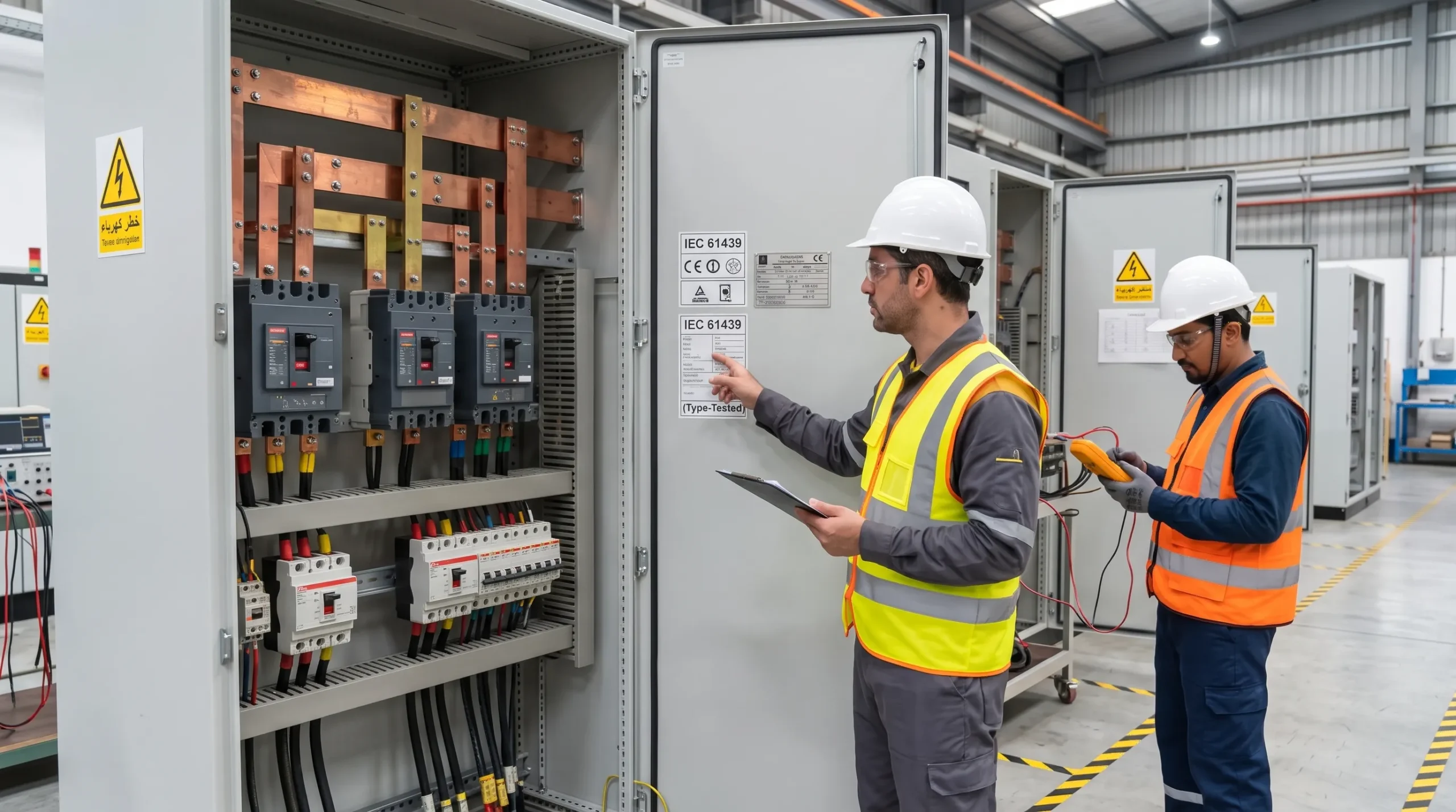
Electrical switchgear serves as the backbone of every manufacturing facility, data center, and commercial infrastructure project. However, the true defense mechanism preventing catastrophic equipment destruction, fire, and extended production downtime rests within the secondary protection system. Comprehensive protection relay testing ensures that numeric relays, sensors, and trip circuits operate with exact precision when overcurrents or short circuits strike. Without thorough pre-commissioning checks, facilities risk catastrophic breaker failure, uncoordinated cascading blackouts, and severe safety hazards. Connecting with certified engineering specialists through Diagnostics & Testing Services guarantees that every protection device operates in full alignment with international reliability standards.
Industrial distribution networks face heavy load swings, surges, and environmental stress. When a line-to-ground fault or thermal overload strikes, the protective relay must make an instantaneous decision. It reads analog inputs, checks them against pre-programmed pickup curves, and issues an immediate trip command to the switchgear. If a relay fails to trip or trips prematurely from improper calibration, the downtime costs escalate rapidly. Partnering with a proven low-voltage panel builder ensures switchgear assemblies integrate fully with compatible control schemes. Rigorous protection relay testing bridges the gap between theoretical calculations and plant safety.
Why Test Protection Relays Before Energization?
Energizing an industrial electrical substation or medium-voltage switchboard without thorough verification is a dangerous gamble. While physical busbars, current transformers, and mechanical breakers can look flawless from the outside, the internal logic and communication wiring of numeric relays require active electrical verification. During transport, panel fabrication, and on-site cabling, multiple vulnerabilities can develop without showing visible external indicators.
Before commissioning, field testing verifies critical operational parameters across the entire protection scheme:
- Control wiring integrity: Technicians verify that current transformer (CT) polarity, secondary grounding, and voltage transformer circuits are correctly wired without short circuits or open loops.
- Relay hardware and internal logic: Testing checks internal analog-to-digital converters, internal power supplies, binary inputs, and output contact continuity under simulated loads.
- Instrument transformer ratio matching: Engineers confirm that CT ratios match the mathematical values used in protection study calculations to avoid calculation errors.
- Trip circuit supervised paths: Tests verify that the complete path between the relay trip output contacts and the breaker shunt trip coil operates reliably without voltage drops.
Factory tests provide baseline quality control but cannot account for field wiring modifications, installation stresses, and local operational parameters. Scheduling on-site Switchgear Testing and Commissioning proves that the relay communicates accurately with associated circuit breakers, interposing relays, and monitoring systems under realistic fault conditions.
How Secondary Current Injection Works
Secondary injection represents the foundational testing method used to evaluate numeric and electromechanical relays. Because injecting thousands of primary amperes through high-voltage busbars requires massive test equipment and poses safety risks, engineers inject calibrated low-level current and voltage signals directly into the secondary terminals of the relay.
Using advanced three-phase microprocessor test sets, field engineers simulate precise fault conditions. A specialized secondary injection test isolates the relay from incoming instrument transformer secondaries, applying exact currents ranging from fractions of an ampere up to multiple times the rated current. The automated test set measures the precise operating time of the relay, comparing actual trip times against standard mathematical time-current characteristic curves.
This method confirms several crucial functional parameters:
- Minimum pickup current accuracy: Testing determines the precise current threshold where the relay initiates timing logic.
- Time-current operating characteristics: Applying multiple multiples of pickup current validates definite-time and inverse-time curves across standard curve bands.
- Reset and drop-out ratios: Verifying the ratio between the pickup threshold and drop-out current ensures the relay resets properly after transient clearance.
- Directional element sensitivity: Phase angle adjustments between injected voltage and current verify directional overcurrent and power flow boundaries.
Modern digital relays contain complex multi-function algorithms, including overcurrent, earth fault, under-voltage, and frequency protections. Facilities integrating smart architectures through Industrial Automation Solutions rely heavily on these intelligent electronic devices. Secondary injection allows technicians to evaluate each individual protection element independently, ensuring that internal firmware logic processes signals correctly without cross-element interference.
Setting Verification Against the Coordination Study
A protective relay is only as effective as the coordination settings programmed into its memory. During the project design phase, electrical consultants generate a formal protective device coordination study. This study evaluates fault levels, motor inrush currents, and transformer curves to establish precise pickup thresholds and time-dial multipliers.
During field commissioning, executing systematic protection relay testing includes formal relay setting verification to ensure stored parameters match the approved coordination study. Discrepancies frequently occur when default factory parameters are accidentally left active or when revised coordination studies are not uploaded to the field devices before commissioning.
The verification process follows a strict engineering sequence:
- Settings file extraction: Technicians download the active configuration file directly from the relay using manufacturer software tools.
- Parameter-by-parameter audit: Field teams cross-reference pickup currents, time delays, curve types, and digital input-output assignments against the stamped engineering study.
- Differential and thermal threshold checks: Verifying specialized elements ensures motor protection curves prevent nuisance tripping during high-inertia mechanical starts.
- Communication protocol mapping: Technicians confirm Modbus, Profibus, or IEC 61850 register mappings so supervisory control systems read real-time measurements correctly.
When settings deviate from the study, selective coordination fails. A minor downstream overload can trip an upstream main incomer, causing an unnecessary plant-wide blackout. Facility teams can consult specialized supply and installation services to guarantee accurate parameter deployment across newly installed switchgear lines.
Trip-Chain and Interlock Checks to Breaker
Verifying that a relay calculates a trip command internally does not guarantee that the electrical circuit breaker will physically open. A complete protection system relies on a seamless chain consisting of auxiliary DC control voltages, trip coils, auxiliary contacts, and mechanical interlocks. A single failure breaks the entire protection scheme.
Engineers perform comprehensive trip-chain testing by allowing the protection relay to close its physical output contacts into the energized breaker trip circuit. This functional test proves that the relay auxiliary contacts can supply sufficient current to actuate the breaker shunt trip mechanism within specified millisecond limits.
Key checkpoints during trip-chain evaluation include:
- DC control stability: Ensuring battery banks maintain voltage during heavy trip coil inrush current.
- Trip circuit supervision: Verifying detection of open circuits, blown fuses, or loose wires across trip paths.
- Lockout relay operation: Testing ANSI 86 lockout relays to ensure breakers stay locked out until manually reset.
- Interlocks verification: Validating key interlocks and transfer schemes to prevent unsafe paralleling.
Simultaneously, engineers conduct an overcurrent relay test using live trip-chain actuation to capture total clearing time. Total clearing time combines the internal algorithmic processing time of the relay with the mechanical opening time of the breaker mechanism, ensuring total fault duration remains safely below equipment damage thresholds. When breakers show signs of sluggish mechanical tripping, plant managers frequently turn to modernization and retrofit services to replace obsolete trip mechanisms with modern vacuum or air units.
Commissioning vs. Routine Maintenance Testing
Facility managers often confuse initial commissioning with recurring preventative maintenance testing. While both utilize secondary injection equipment, recurring protection relay testing addresses long-term component drift, whereas commissioning establishes initial baseline performance.
Commissioning occurs prior to initial plant energization or following substantial system retrofits. It encompasses a complete baseline evaluation of all secondary components, including CT ratio and polarity checks, wiring continuity verification, logic scheme validation, and end-to-end trip testing. Commissioning establishes the definitive benchmark performance profile against which all future maintenance tests will be compared.
In contrast, routine maintenance testing focuses on verifying ongoing operational reliability and detecting component degradation caused by heat, humidity, dust, and electrical stress:
- Periodic functional injection: Checking pickup levels and trip times every two to three years ensures internal electronic calibration has not drifted.
- Contact resistance and cleanliness: Inspecting physical terminal blocks and output contact surfaces prevents high-resistance connections from blocking trip signals.
- Auxiliary power supply evaluation: Monitoring internal electrolytic capacitors and DC ripple prevents sudden electronic power failure inside microprocessor relays.
- Event recorder and fault record analysis: Reviewing stored disturbance records identifies transient faults, harmonic distortion, and intermittent system disturbances before outages occur.
Implementing scheduled electrical audits through structured maintenance services guarantees that switchboards maintain their operational integrity over decades of continuous heavy industrial use.
What Should a Relay Test Report Contain?
A formal protection relay test report is a critical engineering and legal asset. It proves that safety equipment meets technical specifications, satisfies insurance mandates, and equips maintenance teams with historical baseline data. Basic pass-or-fail checklists are entirely inadequate for industrial facilities.
International standards established under the IEC 60255 Series define rigorous test protocols and measurement tolerances for electrical relays. A comprehensive, professionally prepared test certificate must contain clear, auditable documentation covering all aspects of the field assessment.
Every professional relay testing dossier should document the following information:
- Equipment nameplate details: Manufacturer, complete model number, serial number, firmware version, and substation panel tag identification.
- Instrument transformer data: Verified CT and VT ratios, accuracy classes, polarity markings, and secondary burden measurements.
- Coordination study references: The document number, revision level, and date of the approved engineering coordination study used for setting verification.
- Recorded secondary injection values: A detailed tabular comparison showing calculated theoretical trip times versus actual measured trip times across multiple fault multiples.
- Breaker mechanism response times: Measured operating times for the relay output contact, auxiliary trip relay, and primary breaker mechanism opening.
- Test equipment certification: Model and serial numbers of the automated secondary injection kit, along with valid calibration certificates traceable to national standards.
The engineering report must conclude with a formal sign-off by a qualified commissioning engineer, confirming whether the protective scheme is safe for immediate energization. Sourcing certified apparatus from reputable low-voltage products suppliers ensures that instrument transformers and relays possess traceable test documentation from the start.
Common Findings That Delay Energization
During pre-commissioning testing, qualified field engineers frequently uncover serious defects that, if left undetected, would lead to immediate catastrophic equipment failure upon energization. Identifying and rectifying these hidden issues is the primary justification for professional testing protocols.
Field testing routinely uncovers recurring installation defects:
- Reversed CT polarity: Incorrect wiring orientation on current transformer secondaries causes directional and differential relays to misinterpret normal load current as an internal fault.
- Omitted or duplicate neutral-ground bonds: Multiple ground connections on secondary CT circuits create parallel current paths, causing false residual current readings and nuisance earth fault tripping.
- Loose terminal screw connections: Thermal cycling and transit vibration loosen control wiring terminals, introducing intermittent open circuits across critical trip paths.
- DC control voltage drops: Undersized control wiring between the battery bank and switchgear creates severe voltage dips during breaker trip coil activation, preventing breaker opening.
- Unsynchronized internal logic flags: Custom programmable logic equations inside modern numeric relays frequently contain inverted binary inputs, preventing legitimate trip signals from reaching output contacts.
Rectifying these defects during commissioning requires simple field adjustments. In contrast, discovering them during a live fault causes explosive equipment damage, severe arc flash hazards, and weeks of costly downtime.
Relay Testing and Engineering Support
Modern industrial infrastructure demands absolute reliability from its electrical distribution systems. As automation expands and production cycles run around the clock, facilities cannot tolerate unverified protection hardware. Implementing systematic protection relay testing safeguards capital investments, protects operating personnel, and ensures uninterrupted industrial operations.
Field specialists utilize secondary injection systems and diagnostic instruments across your facility lifecycle. Whether commissioning new switchgear, upgrading electromechanical relays to digital IEDs, or conducting maintenance audits, expert technical execution ensures plant reliability.
Partnering with accredited engineering specialists guarantees that every relay is verified against rigorous international standards, including IEEE C37.90 Standards and manufacturer specifications. Professional testing teams provide clear, auditable reporting that satisfies regulatory inspectors, insurance underwriters, and facility managers alike. When you are ready to ensure complete system safety, reach out to our team to contact us and request engineering support before energization begins.