

 العربية

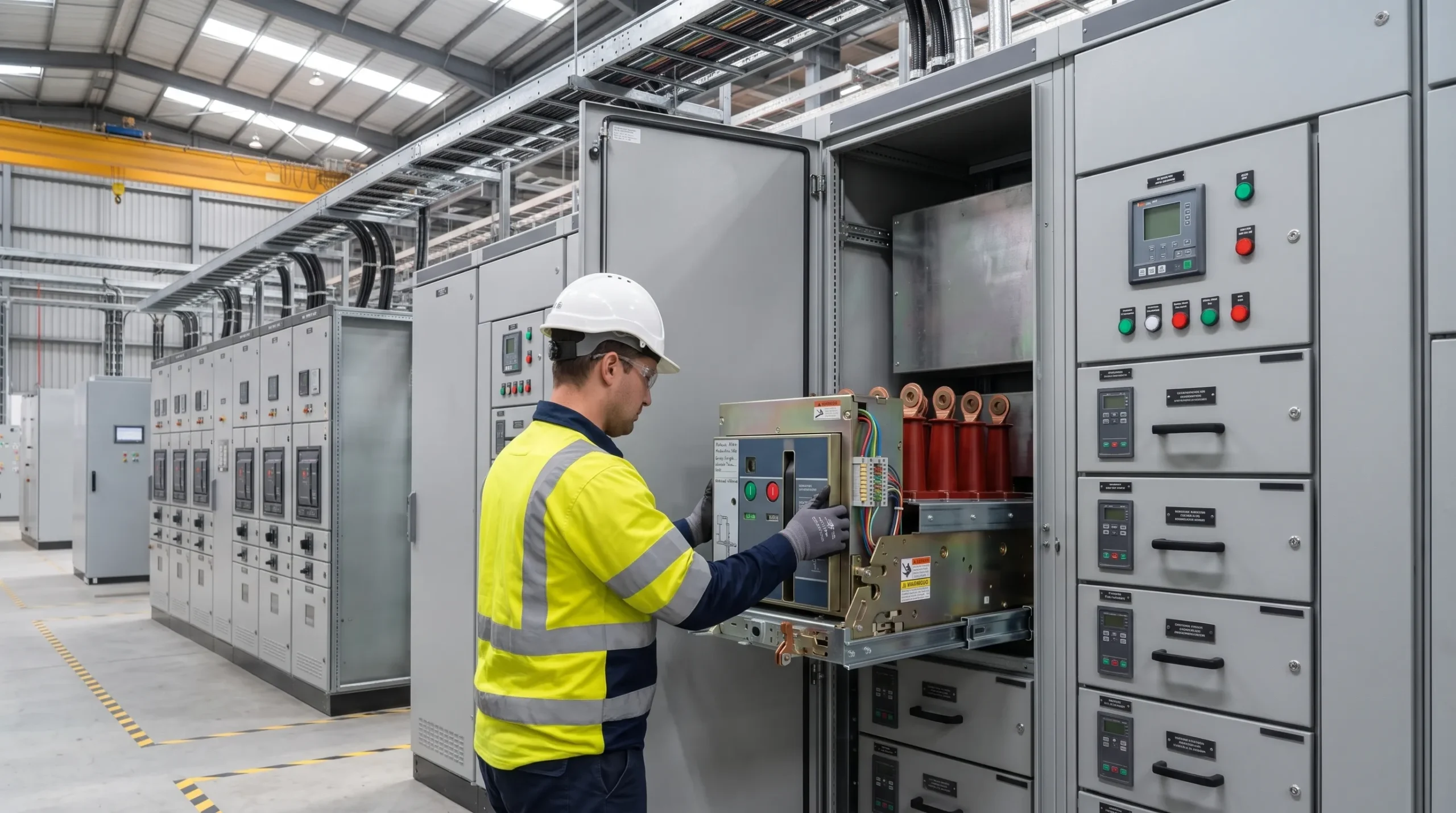
Operating an industrial plant or commercial infrastructure facility requires continuous, dependable electrical distribution. Low voltage switchboards form the backbone of this infrastructure, channeling power to critical production lines, refrigeration plants, water treatment pumps, and data centers. At the heart of these switchboards sits the air circuit breaker (ACB). However, as equipment crosses the twenty-year threshold, maintaining aging switchgear becomes an operational bottleneck.
When original equipment manufacturers discontinue product lines, facilities face a critical strategic decision: should they replace the entire low-voltage switchboard or modernise the existing cubicle? Executing a targeted circuit breaker retrofit provides a practical, cost-effective engineering solution that restores system reliability while avoiding massive capital expenditure and prolonged downtime.
Plant managers and electrical engineers frequently struggle with legacy switchgear that remains structurally sound while its active clearing devices present severe operational liabilities. When spare parts disappear from commercial distribution, routine servicing becomes an exercise in improvisation. Installing a modern breaker into an existing compartment bridges the gap between mechanical longevity and contemporary digital protection. Through engineering best practices outlined by the IEEE Power and Energy Society, legacy power distribution equipment gains state-of-the-art trip units, advanced metering, and seamless SCADA connectivity without disturbing existing power cables or structural busbar networks.
When Is an Air Circuit Breaker Obsolete?
Equipment obsolescence in power distribution does not happen overnight. Manufacturers generally structure product life cycles into active, classic, limited, and obsolete phases. An air circuit breaker enters the obsolete stage when the manufacturer ceases production of core components, stops stocking renewal parts, and terminates formal technical service support. Across manufacturing centers in Egypt, facilities continue to run older switchboards equipped with discontinued models such as the ABB Novomax and Megamax series, Schneider Masterpact M units, or early Siemens and Merlin Gerin breakers. Many facilities consult specialized Maintenance Services to audit whether legacy equipment has surpassed safe operating thresholds before failure occurs. While the copper busbars, sheet metal cubicles, and mechanical structures may show negligible wear, the internal clearing mechanisms and electronic trip units reach the end of their design life.
Operating obsolete breakers introduces distinct operational risks:
- Unavailability of Critical Spares: Moving contacts, arc chutes, mechanical linkages, charging motors, and closing coils can no longer be procured through authorized channels. Sourcing used components from secondary markets introduces severe reliability risks, unverified operating histories, and counterfeit components.
- Degradation of Trip Units: Older analog or first-generation digital trip units suffer electronic drift caused by aged electrolytic capacitors and thermal breakdown of resistors. Over time, these trip units fail to clear overloads accurately or experience nuisance trips that interrupt production, violating maintenance safety benchmarks defined in NFPA 70B Standard for Electrical Equipment Maintenance.
- Mechanism Jamming and Grease Hardening: After decades in service, factory lubricants dry into a tacky paste. When an electrical fault occurs, sluggish mechanical latches slow opening times, increasing the total let-through energy (I2t) and raising the risk of equipment damage.
- Absence of Modern Safety and Communication Protocols: Obsolete units lack arc-flash reduction maintenance switches (ARMS), zone-selective interlocking (ZSI), Modbus or Ethernet communication, and embedded power quality metering.
When replacement parts require multi-week lead times or cannot be certified under modern quality standards, an obsolete breaker upgrade becomes essential to safeguard operational continuity.
Retrofit Kit or Full Board Replacement?
When addressing end-of-life breakers, engineering teams must evaluate whether to commission a brand-new switchboard or modernize the existing assembly. Both approaches present engineering trade-offs that directly affect capital budgets, scheduled shutdowns, and operational risk.
A full switchboard replacement replaces everything from the ground up, including the sheet metal structure, horizontal and vertical busbar systems, incoming cable terminations, and outgoing feeders. While this delivers brand-new switchgear built under modern Panel Building practices, it represents the most disruptive path available. In established plants, power cables enter through congested floor trenches or overhead cable ladders. Pulling, re-routing, and re-terminating hundreds of heavy copper conductors creates substantial physical risk, potential insulation damage, and extended plant shutdowns that manufacturing schedules rarely tolerate.
Conversely, an engineered retrofit kit targets only the active switching and protective elements while leaving the static switchboard structure intact. High-quality copper busbars and structural sheet metal enclosures rarely degrade over time when operating in climate-controlled switchgear rooms. Modernization methods fall into three standard engineering categories:
- Direct Replacement (Plug-and-Play): The replacement breaker is manufactured with identical primary disconnecting contacts, racking mechanisms, and secondary terminal connections to match the original cradle. The old moving breaker is racked out, and the new breaker is racked in without mechanical alterations to the switchboard.
- Cradle-in-Cradle Retrofit: When the original cradle cannot be retained safely, a custom adapter cradle mounts directly inside the legacy compartment. Dedicated copper busbar links bridge the terminals of the new cradle to the switchboard’s original vertical busbars.
- Hard Bus Retrofill: The original fixed or drawout cradle is completely removed. New structural mounting plates, mechanical interlocks, custom-shaped copper busbar adapters, and secondary terminal blocks are permanently installed in the cubicle.
By focusing purely on the breaker mechanism, facilities achieve the reliability of modern technology at a fraction of the cost. To evaluate how these engineering methods apply to specific site installations, facilities frequently consult Modernization & Retrofit Services to review feasibility and switchboard architecture.
Compatibility Checks Before Ordering a Retrofit
A successful switchgear modernization project relies on rigorous field verification prior to manufacturing adapter hardware. Because switchboard manufacturers often introduced minor dimensional modifications across production runs, relying solely on generic model numbers can lead to installation issues on site. A comprehensive site audit ensures that the incoming equipment fits accurately into the existing enclosure.
1. Nameplate Ratings and Fault Capacity
Engineers must verify the continuous current rating (In), rated operating voltage (Ue), and short-circuit breaking capacity (Icu and Ics) per IEC 60947-2 Low-Voltage Switchgear and Controlgear. The new breaker must match or exceed the original fault withstand ratings of the system. In addition, the short-time withstand current (Icw) must be evaluated to ensure downstream selective coordination remains intact during short-circuit events, coordinating reliably with certified Low Voltage Products across the network.
2. Compartment Dimensions and Phase Pitch
Physical measurements inside the de-energized cubicle must confirm the internal clearance, mounting plate bolt holes, and busbar phase-to-phase spacing. Variations in factory busbar droppers can affect how adapter plates line up. Checking the terminal orientation—whether horizontal, vertical, or front-connected—determines the exact copper bending profile required for the supply kit, following manufacturing tolerances established by Schneider Electric Retrofit Technical Guides.
3. Auxiliary Control Circuits and Mechanical Interlocks
Low voltage air circuit breakers integrate with automated control schemes, including emergency stop loops, automatic transfer systems, and remote telemetry. Connecting these panels seamlessly into site-wide control architectures requires alignment with Industrial Automation Solutions. The engineering audit must document:
- Charging motor supply voltage (AC or DC).
- Shunt opening release and undervoltage release coil ratings.
- Closing coil operational voltages.
- Secondary disconnect pin layouts and terminal numbering.
- Mechanical interlocking mechanisms, such as Bowden cables, door interlocks, and key locks (Castell or Ronis) used for safety sequencing.
Thorough technical preparation prevents unexpected site modifications when executing a legacy breaker replacement, ensuring that the installation proceeds smoothly within the scheduled shutdown window.
How Long Is the Outage Window for a Breaker Retrofit?
Production downtime represents the single largest indirect cost in electrical modernization projects. In modern continuous-process facilities such as glass manufacturing, textile weaving, chemical processing, and food packaging, unplanned or prolonged shutdowns can cost thousands of dollars per hour. Comparing the shutdown profiles of switchboard replacement versus targeted retrofit demonstrates why modernization is the preferred operational strategy, especially when coordinated with backup assets through Critical Power Solutions.
A full low voltage switchboard replacement typically demands an outage window lasting anywhere from 72 hours to two weeks. The switchgear room must be cleared, old enclosures unbolted and rigged out, new foundations set, new panels anchored, existing power cables untangled and pulled into new cable boxes, and hundreds of terminations crimped and torqued. Each step introduces potential points of failure, including pinched insulation, inadequate cable bending radii, and wiring cross-connections as cautioned in IEEE Std 3006.7 Recommended Practice for Determining the Reliability of 480 V Switchgear.
In stark contrast, a pre-engineered circuit breaker retrofit requires an outage window of only 4 to 8 hours per breaker. Because the switchboard enclosure and main power cables remain completely undisturbed, the work can be organized around planned maintenance shifts, weekend slowdowns, or night turnarounds. In facilities with dual-incomer switchboards connected via a bus tie (Main-Tie-Main configuration), the upgrade can often proceed without shutting down the entire plant. Loads are shifted to one busbar section, enabling engineers to retrofit the isolated breaker safely while the plant maintains partial or full production.
Advanced planning ensures that all structural components, custom copper links, pre-wired terminal blocks, and lifting trolleys are staged in the switchgear room prior to de-energizing the cubicle. This preparation minimizes lost production time and keeps the project on schedule.
Short-Circuit Ratings and Protection Settings After Retrofit
Installing a modern air circuit breaker into an older switchboard upgrades both the physical switching device and the brain of the electrical distribution system. Legacy mechanical or primitive solid-state trip units provided rudimentary protection curves with wide tolerance bands. Modern units such as modern digital trip units documented in the ABB Switchgear Retrofit Solutions Guide deliver true root-mean-square (RMS) current sensing, micro-adjustable timing bands, and precision fault clearance.
When upgrading a breaker, the short-circuit rating of the retrofit assembly must align with the prospective short-circuit fault levels calculated at the switchboard busbars. The breaking capacity (Icu) of modern breakers easily meets or exceeds older standards. However, engineers must verify that the connection busbar adapters do not introduce electrodynamic weakness during short-circuit events. Quality retrofit kits undergo rigorous short-circuit type testing per IEC 61439-1 Low-voltage switchgear and controlgear assemblies to verify mechanical withstand under high peak current (Ipk) conditions.
Furthermore, integrating a new trip unit requires reviewing the facility’s existing coordination study. Modern trip units feature advanced adjustments:
- Long-Time Protection (L): Protects conductors against thermal overload with adjustable inverse-time (I2t) curves.
- Short-Time Protection (S): Protects against short-circuit faults with intentional time delays to allow downstream molded case circuit breakers (MCCBs) to clear local faults without tripping the main incomer.
- Instantaneous Protection (I): Clears severe short-circuit faults immediately, minimizing damage to switchboard busbars.
- Ground-Fault Protection (G): Detects low-magnitude leakage currents to ground, preventing high-impedance thermal burnouts.
Upgrading trip units provides an opportunity to deploy Arc Flash Reduction Maintenance Systems (ARMS). When maintenance personnel work on energized equipment downstream, flipping a local switch activates an instantaneous pickup setting with zero intentional delay. If a flash occurs, the retrofitted breaker clears the fault in tens of milliseconds, dramatically reducing incident energy and safeguarding operating personnel according to guidelines established in OSHA 1910 Electrical Safety-Related Work Practices.
Testing and Recommissioning the Retrofitted Breaker
Before re-energizing a newly retrofitted air circuit breaker, rigorous on-site quality assurance testing verifies mechanical integrity, electrical insulation, and protection accuracy. Rushing through commissioning introduces significant operational risk. A structured commissioning protocol ensures compliance with international standards and OEM specifications.
The site commissioning protocol consists of five core technical stages:
1. Mechanical Alignment and Interlock Verification
The breaker chassis must be racked in, disconnected, test-positioned, and racked out across multiple mechanical cycles. Technicians inspect the primary isolating contacts to confirm adequate wiping action, proper contact spring pressure, and full engagement depth within the stationary tulip clusters. All mechanical door interlocks, compartment shutter lifting bars, and trip-free mechanisms are confirmed to operate without binding.
2. Insulation Resistance Testing
Using a calibrated high-voltage insulation tester, insulation resistance is measured at 1000V DC across phase-to-phase and phase-to-ground barriers with the breaker closed, and across open contacts. Readings must comfortably exceed minimum industry standards (typically greater than 100 Mega-ohms) to ensure that installation dust, humidity, or damaged insulation blocks do not cause tracking faults upon energization. Field engineers typically reference NETA Acceptance Testing Specifications to certify insulation dielectric boundaries.
3. Contact Resistance Measurement (Ductor Test)
A micro-ohmmeter applies a calibrated direct current (typically 100A DC) across each pole of the breaker, including the newly installed busbar adapter joints. High contact resistance indicates loose fastening hardware, misaligned primary finger clusters, or surface oxidation. Every joint must fall within strict micro-ohm tolerance thresholds, and torques on all bolted copper transitions must be verified with a calibrated torque wrench.
4. Secondary Injection Protection Testing
Secondary injection sets simulate overload, short-circuit, and ground fault conditions directly into the digital trip unit. Technicians inject test currents to confirm pickup thresholds and trip curve timing against the engineer’s protection coordination study. The secondary injection device also confirms that trip solenoids operate reliably and that trip indicators reset properly, upholding test methods detailed in Megger Circuit Breaker Testing Standards.
5. Control Circuit and Remote Signal Cycling
The external auxiliary wiring must be verified under actual control voltage. Engineers test local and remote electrical close and trip commands, verify spring-charging motor cycling, and confirm that status signals (breaker open, closed, tripped, racked in, racked out) correctly communicate back to the plant SCADA or power monitoring system. Facilities needing on-site verification frequently coordinate with Diagnostics & Testing Services to ensure complete compliance prior to hand-off.
What Does a Retrofit Cost Compared with Replacement?
Financial decision-makers require clear economic justification before committing capital to switchgear upgrades. When comparing an ACB retrofit to a comprehensive switchboard replacement, the total cost of ownership (TCO) analysis strongly favors retrofitting. Evaluating project finances requires looking beyond equipment purchase prices to assess total installed cost, civil expenses, and production losses.
The primary economic drivers include:
- Direct Equipment Savings: Purchasing a replacement air circuit breaker equipped with custom mechanical and electrical adaptation hardware typically costs between 25% and 40% of the price of an equivalent new low-voltage switchboard lineup.
- Avoidance of Cable Infrastructure Replacement: Power cables represent an enormous capital investment. Reusing existing power cables eliminates the purchase of new cable runs, reduces cable pulling labor, and avoids modifications to underground trenching and overhead trays. Engineering calculations published by Eaton Electrical Engineering Services confirm that cable re-termination constitutes up to half the labor budget of new panel projects.
- Elimination of Civil and Building Works: Installing new switchboards frequently demands structural modifications to switchgear rooms, cutting new concrete trenches, lifting heavy enclosures through doorways, or upgrading building ventilation systems to fit new equipment layouts. A retrofit fits entirely within the existing switchgear footprint.
- Minimized Production Downtime: Because a retrofit requires an outage of only hours rather than days, facilities avoid major revenue losses associated with idling manufacturing processes. Production lines resume normal operation quickly, turning what could have been a multi-day shutdown into a routine maintenance turnaround.
When evaluated across an operational horizon of ten to fifteen years, modernizing existing low-voltage boards yields substantial financial savings while extending the life of current assets.
Assessing Your Breakers with ARC
Executing a successful switchgear modernization project requires specialized engineering expertise, precise dimensional auditing, and high-level installation standards. Plant environments present unique operational challenges, ranging from high ambient temperatures and dust accumulation to tight maintenance schedules. ARC Technologies delivers end-to-end engineering solutions for facilities looking to modernize their aging electrical infrastructure without incurring unnecessary downtime.
Engineering teams assess existing electrical installations through comprehensive, non-intrusive on-site surveys. Technicians evaluate breaker wear, record compartment dimensions, map auxiliary control systems, and examine thermal conditions across busbar terminations, often integrating Power & Control Products Distribution hardware to modernize sub-distribution levels simultaneously. From engineering custom copper adaptation assemblies to providing complete secondary injection testing, ARC manages the entire modernization process from initial audit to final recommissioning.
By pairing modern digital circuit breakers with proven switchboard engineering, industrial facilities achieve increased plant safety, modern communications, and long-term operating reliability.
Ready to Upgrade Your Legacy Switchgear Without Extended Downtime?
Do not let discontinued air circuit breakers expose your plant to unexpected outages, safety hazards, and hard-to-source spare parts. Protect your operations with a precision-engineered modernization strategy.
Schedule a Comprehensive On-Site Switchgear Audit Today
Contact the engineering specialists at ARC Technologies or explore our complete Modernization & Retrofit Services to review your single-line diagrams, check breaker compatibility, and secure a zero-disruption retrofit plan tailored to your plant schedule.