

 العربية
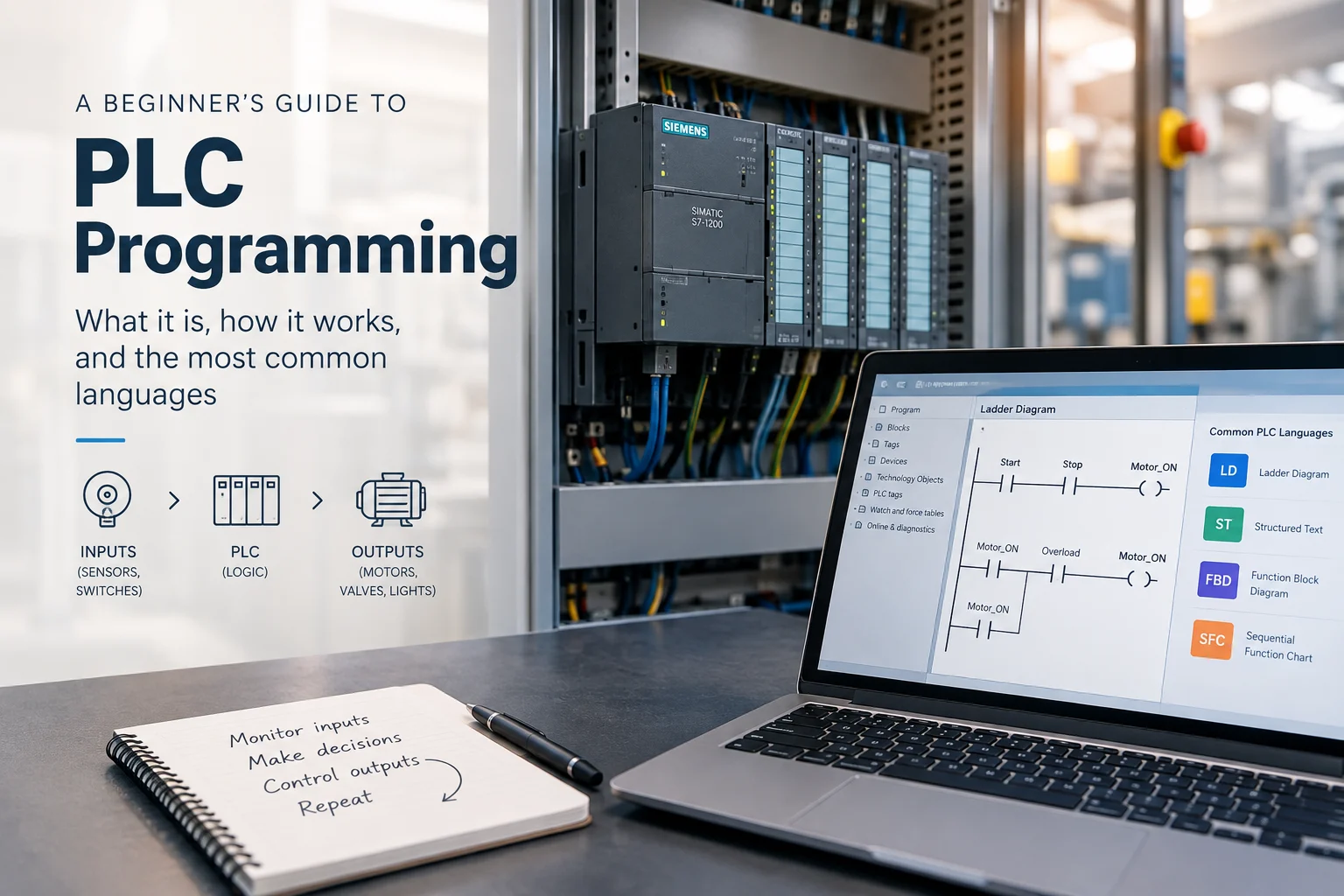
PLC programming is the process of creating the logic that tells a programmable logic controller how to monitor inputs, make decisions, and control industrial equipment. Programmable logic controllers are a core part of many modern production lines, packaging systems, and utility processes. Learning to read and write PLC logic is one of the most practical skills a facility team can develop because it helps technicians and engineers diagnose problems faster and make controlled equipment changes without relying on outside support for every adjustment. This guide explains what PLC programming involves, how the most common PLC programming languages work, and where beginners often go wrong.
What Is PLC Programming?
PLC programming is the process of writing the instructions that tell a programmable logic controller how to respond to real-world inputs, such as sensors, switches, and push buttons, by controlling outputs like motors, valves, lights, and alarms. The PLC processes input information, executes its programmed logic, updates outputs according to the controller’s configuration, and repeats this process continuously. This repeating process is known as the scan cycle, and its duration depends on the controller, program size, and configuration.
Unlike a conventional computer program that might run once and finish, PLC logic is designed to execute continuously while the controller is operating. That distinction matters for anyone learning to write PLC logic. Every rung, function block, or section of code needs to be considered in terms of how it will behave when the controller executes it repeatedly and responds to changing process conditions.
The controller itself is only part of the picture. It works with the industrial automation hardware around it, including sensors, drives, actuators, and human-machine interfaces, to form a complete control system. Before learning PLC programming, it is useful to understand what a PLC is, how its hardware works, and how it interacts with the rest of an industrial automation system, an area ARC Technologies covers as part of its Industrial Automation Solutions.
Ladder Logic in PLC Programming: How It Works
Ladder logic, also called Ladder Diagram (LD), is one of the most widely used PLC programming languages and is a common starting point for beginners. Its visual structure was influenced by the electrical relay control diagrams used in industrial machinery before programmable controllers became widespread. This makes ladder logic familiar to many electricians, maintenance technicians, and control engineers. ABB, whose control solutions ARC Technologies integrates as an ABB partner, traces its own PLC lineage back to the early 1970s, around the same period ladder logic began replacing hard-wired relay panels.
A ladder diagram is organized into horizontal rungs between vertical rails. Each rung represents a logical operation or control condition. Contacts represent conditions that determine whether logic can continue through the rung, while coils and other instructions can control outputs or internal variables.
A simple example is a start-and-stop motor circuit. The logic can use a start command and a stop condition to control a motor output. A holding or seal-in contact can then maintain the motor command after the start button is released, provided the required operating conditions remain satisfied.
The concept can be simplified as:
Start command + safe operating conditions → Motor ON
When the start command is released, the holding logic can maintain the motor command until the stop condition or another interlock breaks the circuit.
Understanding this basic pattern helps beginners recognize more complex ladder programs later, where additional conditions may include motor overload status, permissive signals, level switches, pressure switches, or communication signals.
Ladder logic is generally organized and evaluated according to the controller’s execution model. Understanding how the controller processes the program is important when troubleshooting timing-related problems or logic that depends on execution order.
Its visual similarity to traditional electrical control diagrams also makes ladder logic particularly useful in environments where electrical and maintenance teams need to understand and troubleshoot control logic.
Other PLC Programming Languages
Ladder logic is not the only option. IEC 61131-3 provides a standardized framework for PLC programming languages and related programming elements used in programmable controller systems. The current 2025 edition specifies Structured Text (ST), Ladder Diagram (LD), and Function Block Diagram (FBD), while Sequential Function Chart (SFC) is used to structure the internal organization of programs and function blocks.
Commonly encountered options include:
- Ladder Diagram (LD): A graphical language that represents control logic using contacts, coils, and other instructions. It is particularly familiar to technicians who have experience with electrical control systems.
- Function Block Diagram (FBD): A graphical language that uses interconnected blocks to represent functions and signal relationships. It can be useful for applications involving process signals, calculations, timers, counters, and other function-based operations.
- Structured Text (ST): A text-based language that supports structured programming constructs such as conditional statements, loops, calculations, and data handling. It can be useful when control logic becomes too complex or data-intensive to represent efficiently with ladder diagrams.
- Sequential Function Chart (SFC): A graphical approach for organizing programs around steps and transitions. It can be useful for machines and processes that move through clearly defined sequences or operating stages.
Instruction List (IL) may still be encountered when working with older PLC systems because it was included in earlier editions of IEC 61131-3. However, it is not part of the current IEC 61131-3:2025 language suite.
The appropriate programming language depends on the controller platform, project requirements, engineering practices, and the type of logic being developed. Some automation platforms also allow different programming approaches to be used within the same project.
Basic Structure of a PLC Program
Although PLC programs vary between manufacturers and applications, most contain several recurring elements.
- Inputs and outputs (I/O): These represent signals exchanged between the PLC and the field. Inputs may include proximity sensors, push buttons, pressure transmitters, or level switches, while outputs may control motors, valves, solenoids, indicators, or other equipment.
- Tags or addresses: Inputs, outputs, internal variables, and data need identifiers that the program can reference. Older systems may rely heavily on fixed memory addresses, while modern platforms often use descriptive tag names to make programs easier to understand and maintain.
- Main logic routines: These contain the primary control decisions executed by the PLC according to the controller’s program structure.
- Subroutines and function blocks: Reusable sections of logic can handle specific functions such as motor control, sequencing, calculations, or PID control.
- Timers and counters: These instructions are commonly used for delays, cycle counting, sequencing, and other time- or event-based operations.
- Data types and structures: PLC programs may use Boolean values for simple on/off states, integers for counts or values, and floating-point data for measurements such as temperature, pressure, or flow.
- Program documentation and version control: Comments, I/O lists, revision histories, backups, and other documentation help teams understand the program and identify what changed between versions.
A well-organized PLC program uses meaningful tag names, logical program structures, clear comments, and consistent documentation. These practices may not change how the machine operates, but they can make a significant difference when another technician or engineer needs to troubleshoot or modify the system later.
How to Start PLC Programming
For beginners, PLC programming is easier to approach when the learning process follows the same logic used in real automation projects.
1. Understand the process
Start by understanding what the machine or process needs to accomplish. Identify its normal operating sequence, required conditions, and expected responses to abnormal situations.
2. Identify the required inputs and outputs
Create a list of the devices that provide information to the PLC and the equipment the PLC needs to control. This may include sensors, switches, motors, valves, actuators, and other field devices.
3. Create an I/O list
An I/O list connects the physical equipment to the controller’s input and output points. It provides a useful reference during programming, testing, commissioning, and troubleshooting.
4. Define the control sequence
Break the process into logical steps. Determine what must happen first, what conditions allow the next step to occur, and what should happen if a required condition is not met.
5. Choose the appropriate programming language
Select the programming approach that fits the controller and application. Ladder logic may be suitable for straightforward discrete control, while Structured Text or other approaches may be more efficient for complex calculations or sequences.
6. Write and organize the PLC logic
Build the program around clear routines, meaningful tags, appropriate interlocks, and reusable functions where applicable. Good organization makes the program easier to test and maintain.
7. Test and simulate the program
Where the platform and project allow it, test the logic before connecting it to production equipment. Simulation and controlled testing can help identify errors before they affect the physical process, the same verification approach ARC Technologies applies through its Diagnostics & Testing Services ahead of commissioning.
8. Commission the system
During commissioning, the PLC program is tested against the actual equipment and process. Inputs, outputs, sequences, communications, alarms, and required operating conditions should be verified.
9. Document the final program
Save the approved program version and update the documentation, I/O lists, comments, and revision history. This creates a useful reference for future troubleshooting and modifications.
Common Beginner Mistakes in PLC Programming
A few mistakes appear repeatedly among people who are new to PLC programming. Recognizing them early can make the learning process much easier.
Skipping documentation is one of the most common problems. A program without tag descriptions, rung comments, I/O information, or revision history can become difficult to maintain when someone other than the original programmer needs to work on it.
Ignoring scan behavior can cause subtler problems. Beginners may assume that PLC instructions execute simultaneously, but the controller processes the program according to its execution model. The timing of input processing, logic execution, and output updates can vary by controller and configuration. Understanding this behavior is important when troubleshooting timing-related problems or logic that depends on execution order.
Overlooking safety requirements is a more serious risk. Emergency stops, guard door switches, overload protection, and other safety functions must be designed, implemented, and tested according to the requirements of the specific machine and applicable safety standards, including OSHA’s requirements for the control of hazardous energy. Depending on the application, safety-related functions may require dedicated safety components or safety-rated control systems rather than standard PLC logic alone.
Testing changes without a controlled process can also create unnecessary downtime. Changing logic directly on a running machine without a documented plan can turn a small modification into a larger production problem. Where practical, teams should back up the existing program, document the planned change, test it in a controlled environment, and verify the result before returning the equipment to normal operation.
For teams building PLC skills, structured Training Services can provide a safer environment for learning these fundamentals before applying them to live industrial equipment.
PLC Programming vs. PLC Engineering
PLC programming is an important part of an automation project, but it is not the same as PLC engineering as a whole.
PLC programming focuses primarily on creating and testing the control logic that determines how the controller responds to inputs and controls outputs. This can include sequencing, interlocks, timers, counters, calculations, alarms, and communication logic.
PLC engineering covers a broader set of activities around the control system. Depending on the project, it can include defining control requirements, developing the I/O architecture, selecting hardware, designing the control system, integrating HMIs and networks, coordinating electrical panels, commissioning the equipment, and documenting the completed system.
Understanding the difference is important because a PLC program cannot be designed effectively without understanding the process and hardware it is intended to control. Good PLC engineering connects the software logic with the electrical, mechanical, and operational requirements of the machine.
How PLC Programming Fits into an Automation Project
PLC programming is one part of a larger industrial automation project. It connects the control requirements of a process with the PLC, sensors, actuators, HMI, drives, networks, and electrical control hardware.
A typical project begins by defining what the process needs to accomplish and under what conditions it should operate. Electrical and control panel design then determines how the controller, drives, protective devices, and other equipment will be integrated.
PLC programming translates the process requirements into control logic. At the same time, HMI development can provide operators with visibility into machine status, alarms, parameters, and operating conditions.
Commissioning and testing follow, allowing the control logic to be verified against the actual equipment and process. Once the system is operational, documentation, troubleshooting, modifications, and future upgrades become part of the system’s ongoing lifecycle.
This is why PLC programming is best approached as part of broader automation and system integration work rather than as a completely standalone task. A program developed without understanding the mechanical constraints, electrical protection, field devices, or operating requirements can require significant changes once it is connected to real equipment.
PLC Programming and Automation Support from ARC Technologies
ARC Technologies supports industrial automation projects involving PLC programming, Panel Building, commissioning, system modifications, and ongoing technical support for facilities across Egypt, the Middle East, and Africa.
As an official ABB partner and official ABB panel manufacturer, ARC Technologies integrates ABB control solutions within industrial electrical and automation systems where they are appropriate for the project requirements. More on this partnership is available on the About Us page.
For existing systems, support may include reviewing and modifying PLC logic, documenting existing programs, expanding control functionality, and upgrading aging automation systems through structured Modernization & Retrofit Services and Maintenance Services. The objective is to ensure that the control logic, electrical hardware, and process requirements work together as part of a coordinated automation system.
Whether you are developing a new machine or upgrading an existing control system, clear programming, appropriate safety measures, structured testing, and proper documentation can help create a system that is easier to operate and maintain.
Planning a new automation project or need to modify an existing PLC system? Contact ARC Technologies to discuss your control requirements, programming needs, and system integration scope.

Leave a comment