

 العربية
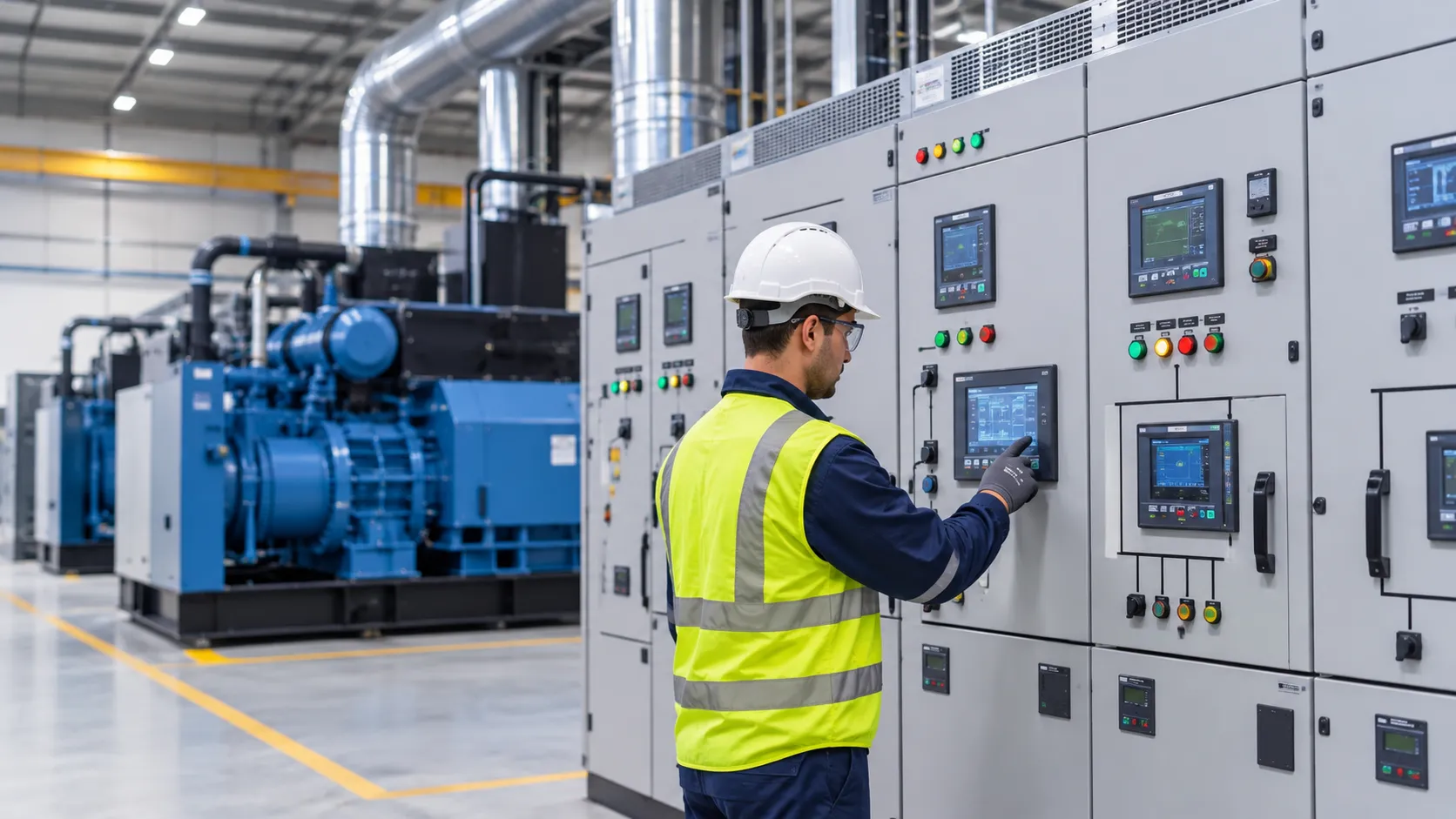
A generator synchronizing panel is the switchgear and control system that lets two or more generating sets connect to one common busbar and share the plant load as if they were a single machine. It matches each incoming set to the live bus, closes its breaker at the right instant, and then keeps the sets sharing kW and kVAr in proportion to their ratings. ARC’s Critical Power Solutions team designs and commissions these systems for industrial and commercial sites, and this guide explains how they work and when you need one.
What Is a Generator Synchronizing Panel?
A generator synchronizing panel is a low or medium voltage switchboard that holds one breaker per generating set, a common bus, and the controllers that synchronize and load-share the sets. In short: it turns several separate generators into one coordinated power plant.
Without it, each set feeds only its own loads. With it, all sets feed one bus, and the controls decide how many sets run, which starts first, and how load is split. Most panels also handle the utility interface.
The engine and alternator side of the picture is covered by ISO 8528-1, which defines application classes and ratings for reciprocating engine-driven generating sets, including the associated switchgear and control gear. The panel has to respect those ratings, because a set rated for prime power behaves very differently from one rated only for emergency standby.
The Four Conditions for Paralleling Two Generators
Before a breaker can close an incoming set onto a live bus, four conditions must be met: phase sequence, voltage, frequency, and phase angle. Get any one wrong, and the closing moment produces a current surge and a torque shock on the engine shaft.
- Phase sequence. L1, L2, and L3 of the incoming set must rotate in the same order as the bus. This is checked once at commissioning and again after any cabling work, because no controller can correct it.
- Voltage magnitude. The incoming voltage should be close to the bus voltage. Typical sync-check windows sit around a 2 to 5 percent difference.
- Frequency. The incoming set runs at a slightly different speed, so the phase angle drifts slowly into alignment. A slip of about 0.1 to 0.2 Hz is common, with the incoming set a little faster so it picks up load rather than absorbing it.
- Phase angle. The breaker closes when the voltage waveforms are nearly on top of each other, usually within about plus or minus 10 electrical degrees.
The synchronizer adjusts speed through the governor and voltage through the AVR until all four values sit inside the window, then issues the close command early enough to allow for the breaker’s own closing time. A separate sync-check relay (ANSI device 25) acts as an independent permissive, so a single failed controller cannot close the breaker out of phase.
How Load Sharing Controllers Balance kW and kVAr
Once sets are in parallel, real power is shared by controlling engine fuel, and reactive power is shared by controlling alternator excitation. These are two separate loops, and both need to be right.
Real power (kW). The governor sets how much fuel the engine burns. In droop mode, speed falls slightly as load rises, typically 3 to 5 percent from no load to full load, and sets with matching droop settings share load naturally. In isochronous mode, the sets hold exact frequency and talk to each other over a load share line or CAN bus so each one carries the same percentage of its rating. Isochronous sharing is the normal choice for island operation because frequency stays at 50 Hz regardless of load.
Reactive power (kVAr). The AVR sets excitation. If one alternator is over-excited compared with the others, reactive current circulates between the sets without doing any useful work, heating windings and pushing one machine toward its current limit while the others look lightly loaded. Voltage droop or a kVAr sharing function prevents this by trimming each AVR so power factor stays roughly equal across the sets.
A well-commissioned system holds sharing within a few percent of rating. If two identical sets sit at 80 and 50 percent, one of these loops needs attention.
When Does a Plant Need Paralleled Sets?
A plant needs paralleled sets when one generator cannot cover the load sensibly on its own, when downtime of a single set is unacceptable, or when the load swings too widely for one machine to run efficiently. Here are the most common triggers:
- Load above a practical single set size. Beyond roughly 2 to 2.5 MVA at low voltage, one large set becomes expensive, heavy to install, and hard to replace quickly.
- Redundancy. An N+1 arrangement lets one set stop for maintenance or failure while the rest carry the load. Data centers, hospitals, and continuous process plants often require this.
- Variable demand. Diesel engines dislike running below about 30 percent load for long periods, because unburnt fuel builds up in the exhaust. Running multiple generator sets lets the controls start and stop machines to keep each running set in its efficient range.
- Large motor starting. Two or three sets on one bus absorb a big motor’s inrush with a smaller voltage dip than any one of them could alone.
ISO 8528-5 is useful here because it specifies performance criteria for generating sets, including sets running in parallel with each other or with the grid. Its performance classes help you match transient response to the load you actually have.
Main Components Inside a Synchronizing Panel
A typical synchronizing panel contains power switching, measurement, control, and protection, all wired back to a common control system. Most include:
- Generator breakers. Motorized air circuit breakers, or MCCBs, one per set, with fast closing times so the sync window is hit accurately.
- Common busbar. Rated for the combined output of the sets plus future expansion, with verified temperature rise and short-circuit withstand.
- Generator controllers. Units from makers such as DEIF, ComAp, or Woodward handle synchronizing, load sharing, and engine protection.
- Measurement transformers. CTs on each generator feeder and VTs on both sides of each breaker, so the controller compares incoming voltage with bus voltage.
- Power management logic. Load demand start and stop, priority selection, load shedding, and restoration of non-essential feeders.
- Mains interface. Where required, a mains breaker, utility protection relay, and import or export control.
- Control supply. Batteries or a UPS so the panel works through a blackout.
Many sites order this equipment as purpose-built synchronizing switchgear from a panel builder rather than adding parts to an existing changeover board. ARC’s Panel Building service covers this kind of assembly, and the breakers, relays and meters themselves can be sourced through Power & Control Products Distribution.
Protection and Interlocks Between Sets and Mains
Protection in a paralleled plant has to cover two risks that a single set never faces: one set driving another as a motor, and the plant feeding back into a utility network that has lost supply.
Between sets, the key functions are:
- Reverse power (ANSI 32). If an engine loses fuel or a governor fails, its alternator draws power from the bus and motors the engine. A setting around 5 to 10 percent of rating with a short delay is common for diesel sets.
- Loss of excitation (ANSI 40). Detects an alternator that has lost field current and is absorbing reactive power from the others.
- Overcurrent and earth fault. Coordinated so the faulty set’s breaker opens without tripping healthy sets.
- Dead bus logic. When all sets start together after a blackout, only one breaker may close onto the dead bus. The others must wait and then synchronize to it.
Between the plant and mains, loss of mains protection (rate of change of frequency or vector shift) separates the generators within a fraction of a second if the utility trips while the plant is in parallel. Breaker interlocks stop the mains and generator breakers from closing together without synchronization. Where continuous mains parallel is planned, the local distribution company usually has to approve the protection scheme first.
Neutral earthing also needs a decision. With several sets star-earthed at once, third harmonic currents can circulate through the neutrals, especially when alternators of different winding pitch run together. Some designs earth only one set’s neutral at a time through switched contactors.
Secondary injection and trip-chain checks by a team such as ARC’s Diagnostics & Testing Services confirm that every relay trips the right breaker at the right setting.
What Goes Wrong During Synchronization?
Most synchronization faults come from wiring errors, poor tuning, or settings that do not match between sets. The common ones are:
- Out-of-phase closing. Caused by wrong VT wiring, a reversed phase after maintenance, or a breaker slower than the controller expects. The result is a loud bang, a current spike, and possible shaft or coupling damage.
- Hunting. Governor or AVR gains set too high make sets swap load back and forth in a slow oscillation.
- Circulating reactive current. Mismatched voltage settings or droop leave one set carrying most of the kVAr.
- Reverse power trips on light load. When load drops, a set can slip into motoring if the power management logic does not stop surplus sets in time.
- Load share line failure. In isochronous systems, a broken communication link can make sets fall out of balance. Good controllers switch to droop as a fallback.
- Mismatched machines. Sets from different makers, or with different alternators, may have different transient responses. Alternator ratings and temperature limits under IEC 60034-1 are worth checking when an old set is paralleled with a new one.
Many show up during load bank tests at commissioning. Others appear months later after a component swap, which is why periodic checks under a planned maintenance services contract are worth having.
Specifying a Paralleling System with ARC
A good specification starts with the load profile, not the generator catalogue. Before asking for prices, collect the following:
- Load data. Peak and minimum demand, largest motor, and any harmonic loads such as drives or UPS systems.
- Operating mode. Island only, short closed transition back to mains, or continuous mains parallel.
- Redundancy target. N, N+1 or N+2, and which loads must never drop.
- Existing equipment. Make, rating, and controller type of any sets already on site.
- Expansion plans. Spare breaker positions and bus rating for future sets.
- Testing scope. Factory acceptance test, site acceptance test with load bank, and the documentation you expect at handover.
With those answers, ARC can size the bus, select controllers that suit your sets, and design protection that your utility will accept. Generator paralleling done this way gives you a plant that starts, shares, and protects itself without operator guesswork. To discuss a generator synchronizing panel for a new plant or an upgrade, contact the ARC Critical Power Solutions team with your single-line diagram and load list.
Can generators of different sizes run in parallel?
Yes. The controllers share load as a percentage of each set’s rating, so a 500 kVA set and a 1000 kVA set can run together at the same per-unit load.
What is the difference between droop and isochronous load sharing?
Droop shares load by letting frequency fall slightly as load rises. Isochronous holds frequency fixed and shares load through communication between controllers.
How long does synchronization take?
A healthy set normally synchronizes within 5 to 15 seconds of reaching rated speed and voltage, depending on controller settings and governor response.
Does a paralleled plant need utility approval?
Island operation normally does not. Any mode that parallels the mains, even briefly, generally needs the distribution company’s approval of the protection scheme.