

 العربية

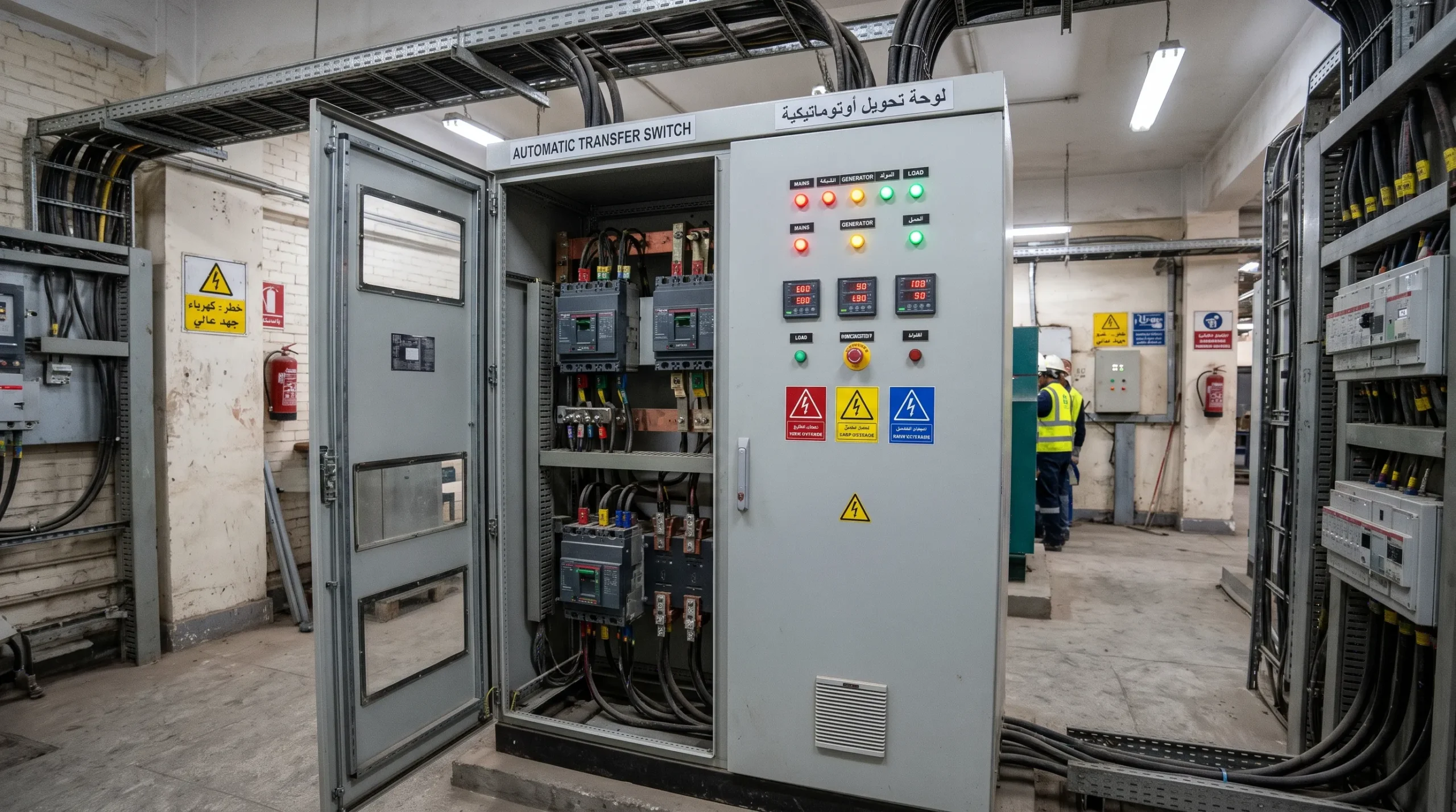
An automatic transfer switch decides, within seconds, whether your plant keeps running when the grid drops. It watches the mains, starts the generator when voltage or frequency moves out of limits, and moves the load across once the set is stable. Egyptian factories felt the value of that when rolling two-hour power cuts began in July 2023 and ran for more than a year.
This guide covers how to pick an automatic transfer switch for industrial backup power: transition types, sizing for motors, transfer time, failure points and the controller settings worth checking before handover. If you are sourcing switching equipment now, our Power & Control Products Distribution team can match the device to your load list.
What Does an Automatic Transfer Switch Do?
It connects a load to one of two sources and normally never to both at the same time. In a typical mains generator changeover, the normal source is the utility feed, and the emergency source is a diesel set. The product standard for this equipment is IEC 60947-6-1, which covers manual, remotely operated, and automatic transfer switching equipment, including the controller.
The sequence is simple. The controller senses a fault on the mains, waits a short confirmation delay, sends a start signal to the generator, waits for stable voltage and frequency, and then transfers. When the mains returns, it waits again before transferring back, then lets the engine run unloaded to cool down. The switch’s integration with UPS units and paralleling gear is part of the wider Critical Power Solutions design.
An ATS panel is the enclosure that holds the switch, controller, bypass, metering, and indication lamps. It must be built and verified like any other assembly, with proper busbar spacing, cable entry, and heat dissipation, which is why the panel-building stage matters as much as the switch you choose.
Open, Delayed, and Closed Transition Compared
Transition type describes what the load sees during transfer: a short gap, a planned pause, or no gap at all. Open transition is break-before-make, and it is the default for most factories because it is simple and cheap. ABB’s Zenith ATS range, for example, is offered in standard, delayed, and closed transition from 30 A to 3000 A.
Delayed transition adds a stable OFF position (I-O-II). The load is held disconnected for a set time before it connects to the other source. This matters for large motors and transformers, because a disconnected motor keeps producing a residual voltage for a short time as it slows down. Closing onto a live source while that voltage is out of phase can produce a current surge large enough to trip breakers. Setting that pause for each motor group is part of our Critical Power Solutions design work.
Closed transition is make-before-break. Both sources are paralleled for a very short overlap, usually around 100 ms, so the load sees no interruption on a planned retransfer. It only works when both sources are live, and it needs the utility’s approval to parallel a generator with the grid, even briefly. Some controllers limit it to specific layouts, as ABB’s TruCONTROL notes for main-tie-main schemes.
Transition | Load interruption | Typical use |
Open (I-II) | Short gap, usually under a second of switching | General plant loads |
Delayed (I-O-II) | Adjustable pause | Large motors, transformers, drives |
Closed | None on planned transfers | Process lines that cannot tolerate a blip during testing |
ATS vs Static Transfer Switch: Which Do You Need?
Most industrial sites need a mechanical ATS, not a static one. A static transfer switch (STS) uses thyristors instead of moving contacts and transfers in a few milliseconds, but only between two sources that are already live. ABB’s Cyberex SuperSwitch 4 is one example: a digital STS that moves a critical load between two live sources, such as two UPS systems.
An STS cannot start a generator and wait for it, which is the whole job in a mains-to-generator scheme. So the usual factory design is a mechanical ATS at the main board, with a UPS covering the sensitive circuits. PLCs, HMIs, and SCADA servers ride through on that UPS, a point we plan for in industrial automation solutions projects.
Static switches also carry conduction losses, so they produce heat all the time and need cooling. In an Egyptian electrical room that already sits above 40°C in summer, that is a real running cost. For most process loads, a mechanical switch from a Low Voltage Products range, plus a UPS where speed truly matters, is the cheaper and simpler choice.
Sizing an ATS for Motor and Inrush Loads
Size the switch on continuous current, utilization category, and short-circuit withstand, not on the breaker rating alone. A 1000 kVA transformer at 400 V has a full-load current of about 1443 A, so a 1600 A frame is the starting point. Then check the utilization category in the IEC transfer switching standard: AC-31 covers non-inductive loads, while AC-33 covers motor loads and mixed loads with motors, which is what most plants actually have.
Motors are the hard part. When a running motor is switched onto a source that is out of phase with its own residual voltage, the inrush can be several times the normal starting current. An in-phase monitor waits until the two waveforms line up before it closes, which keeps that surge under control. It is a standard controller setting on most modern switches, as the ABB Zenith T-series manuals show.
The generator side matters too. A big motor step causes a voltage dip and frequency drop on the set, and the ATS will see that as a bad source if its limits are tight. ISO 8528 defines performance classes G1, G2, and G3, with G3 aimed at loads that need stable, accurate power.
Finally, the withstand and closing rating has to match the prospective fault level at the board, coordinated with the upstream breaker. On older boards, this is often where problems hide, and an upgrade through Modernization & Retrofit Services should include checking that the existing switch still matches today’s fault level.
How Long Does a Transfer Take, and Does It Matter?
A mains-to-generator transfer usually takes around 10 seconds, and almost all of that is the engine starting and settling. The switch mechanism itself moves in a fraction of a second. NFPA 110 classifies emergency power systems by type, class, and level, and a Type 10 system must restore power to the load within 10 seconds.
The rest of the delay is deliberate. A short outage confirmation timer, often 1 to 3 seconds, stops the generator from starting on every grid flicker or auto-reclose. A longer return timer, often several minutes, makes sure the mains have really stabilized before the load goes back. Modern controllers such as ABB’s TruCONTROL expose each of these as separate adjustable time delays.
Whether 10 seconds matters depends on the load. Drives, PLCs, and chillers often drop out within tens of milliseconds and may need a manual reset, so they need a UPS or ride-through settings. The requirements of NFPA 110 are a good reference for separating life-safety loads from loads that can wait.
Typical ATS Failure Points and How to Avoid Them
Most ATS failures are not dramatic. They come from neglect, wrong settings, or a switch that was never tested under real load. These are the ones we see most often on site visits and during Maintenance Services calls:
- Dead controller supply. A flat battery or a blown sensing fuse leaves the controller blind, so it never sees the outage.
- Worn or pitted contacts. Every transfer under load erodes the contacts a little, and high resistance turns into heat.
- Loose terminations. Vibration and heat cycles loosen lugs over time, and they show up clearly on an infrared survey.
- Neutral and earth-fault trips. A 3-pole switch on a system that needs a switched neutral can cause nuisance earth-fault trips on the generator.
- Never exercised. A switch that sits for two years in one position may stick the first time it is needed.
Heat is the early warning for the second and third points. A thermographic survey and a contact resistance test, both part of our Diagnostics & Testing Services, will usually find a failing switch months before it fails.
The maintenance side is getting more formal too. The 2026 edition of NFPA 70B added a dedicated chapter on transfer switch equipment, covering switches rated up to and above 1000 V. Even where it is not enforced, it is a sound basis for a site maintenance plan.
Controller Settings to Review at Commissioning
Factory defaults are a starting point, not a setting sheet for your site. Each value below should be checked against the generator data, the load list, and the local grid behavior, then recorded in the commissioning test report:
- Undervoltage and overvoltage pickup and dropout on the normal source
- Under- and over-frequency limits, wide enough for the generator’s transient dip
- Phase sequence check on both sources
- Outage confirmation delay and engine start delay
- Transfer delay to the emergency source after the set is stable
- Return delay to mains and engine cool-down time
- Center-off time on delayed transition switches
- In-phase or in-sync window, if the controller has one
- Exercise timer: day, duration, and whether it runs with or without load
The in-phase window is worth a closer look on motor-heavy plants. Defaults differ between makes and models, so confirm on site that the monitor is switched on wherever large motors are fed. Check the setting against the documentation for your Zenith or TruONE switch rather than assuming the factory value.
After the settings are entered, test with the real generator and a real load, not just the test button. Pull the mains, time each step, and compare against the sheet. Older switches with no event log can often be fitted with a new controller through our Modernization & Retrofit Services, which also brings remote monitoring.
Choosing a Transfer Switch for Your Facility
Start from the loads, not the catalogue. List what must run on the generator, what can be shed, and which motors start on transfer. Then decide the transition type, frame size, number of poles, and controller level. Comparing transfer switch types on price alone tends to miss the costs that come later: nuisance trips, unplanned stops, and a controller nobody on site can read.
A good automatic transfer switch selection usually ends with a short specification: rated current and utilization category, withstand rating, transition type, 3 or 4 poles, bypass needs, communications, and the full settings sheet. ARC supplies switches and builds the panels around them through Power & Control Products Distribution, and we can review your backup scheme as part of a wider Critical Power Solutions study.
Frequently Asked Questions
How often should an automatic transfer switch be tested?
Exercise it monthly with the generator, ideally under real load, and do a full inspection and maintenance at least once a year. Healthcare rules are stricter: NFPA 99 asks for a monthly visual inspection of transfer switches, and NFPA 70B can push full testing to every year depending on equipment condition.
Can an ATS be added to an existing main board?
Usually yes, either as a separate ATS cubicle beside the board or as a section added to it. The busbar rating, fault level and available space decide which route works, and a site survey through Modernization & Retrofit Services will confirm it before you order.
Do I need a 3-pole or a 4-pole transfer switch?
It depends on the earthing system and how the generator neutral is bonded. If the generator is a separately derived source with its own neutral-earth bond, a 4-pole switch with a switched neutral is normally needed to avoid earth-fault trips. Our Low Voltage Products team can help you choose the right pole count.